
Thingiverse
Right Angle Edge Guide for Festool ETS EC125/3 EQ


- Creator (as listed at the source)
- supergimp
- Licence
- Creative Commons - Attribution - Non-CommercialStated at the source marketplace; SliSearch does not verify licences.
- File types
- STEP STL
- Pricing
- Free
- Published
- Category
- Tools
- Likes
- 173
Overview
Since Festool doesn't make a right angle edge sander for this model, and inspired by the design here: I decided to design and print my own. I had to remodel everything, and in the end I only borrowed the design of the base plate from that design but changed it a bit and designed my own mounting system. The print requires inserting several M4 nuts mid-print. I do this in PrusaSlicer by defining a layer pause once the cavities for the nuts are complete but before they are covered over by the next layer. The following parts have embedded hardware (assuming 0.2mm layer height): Arm - Print vertically and pause at layer 56 to insert four (4) M4 nuts. Ref Surface - Print flat on build surface and pause at layer 216 to insert four (4) M4 nuts. Rounded Knob (2) - Similarly, pause on layer 29 to insert two (2) M6 nuts. The Handle, Clamp and Ref Surface have modeled M6 threads for attaching clamping knobs and handle. You will probably need to run an M6 tap through the finished print to clean the threads. For the Handle, I used a short (~25mm) length of M6 threaded rod to attach the Handle to the sloped face of the Ref Surface. For the Clamp and Clamp Base, I used two pieces (~30mm) of M6 threaded rod and added a small drop of epoxy to the threads before screwing them into the Clamp Base to create two studs for the Rounded Knobs. The Clamp Base is held to the Arm with four (4) 20mm M4 button head machine screws. The Arm is held to the Ref Surface with two (2) 20mm M4 and two (2) 12mm M4 button head machine screws. Hardware necessary: 6 - M4 button head machine screws, 20mm 2 - M4 button head machine screws, 12mm 8 - M4 nuts 2 - M6 nuts 2 - M6 threaded rod, ~30mm 1 - M6 threaded rod, ~25mm One note about assembly: Check the reference surface against the sanding pad for square, especially in the position in which you intend to use it (the clamp assembly can be rotated to place the Ref Surface to the front or either side of the sander body). The alignment can change slightly depending on the rotation of the arm. I positioned mine as I wanted to use it and then checked for square and found that I had to slightly shim the Clamp Base to Arm connection with a small slip of paper to get a perfectly square alignment.
Print this with Prinnu
- Download the model file from the source page. SliSearch moves no files.
- Upload the file at slicience.com/quote. Prinnu quotes it in minutes.
Similar models
Chosen by shared tags first, then category. Each one links to its own marketplace.
 Festool ETS EC150.5 EQ 90 degree sander bracketThis is a printable 90-degree mount to hold the FESTOOL ETS EC 150 sanders at a perfect right angle to the work surface. Allows you to sand bench top edges at exactly 90 degrees without rounding over the edges accidentally.
 Perpendicular Drilling Jig (universal)This drilling jig is for drilling holes perpendicular to a surface. Easily adapted to tools from other manufacturers.
 Festool Abrasive holder with positioning aidFestool Abrasive holder with positioning aid - simplify your tool management Where do you currently store your abrasives?
 Festool Guide rail holderFestool Guide rail holder - simplify your tool management Where do you currently store your guide rail? Print your own Festool guide rail holder and make your everyday work easier and more productive.
 Universal Cordless Drill/Driver Holder/Mount (Milwaukee, Makita, DeWalt, Bosch, Ryobi, Ridge, Festool)
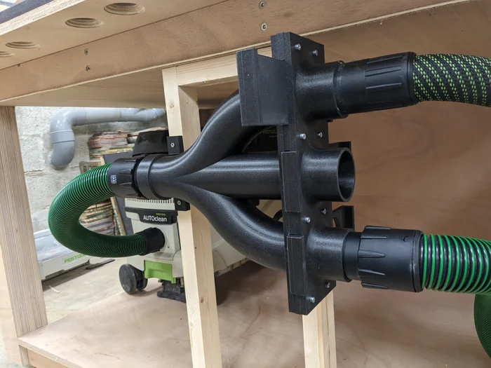 3-way blast gate for Festool hosesHere's the 3-way blast gate I use in my shop, powering my portable tools, router table and table saw. It's hooked to a Festool dust extractor and connects to the tools using various Festool hoses, since most (all?) Festool connectors are...
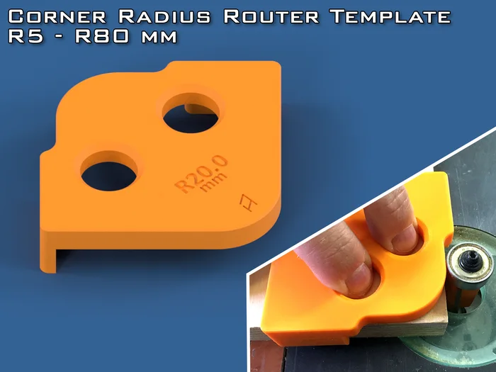 Corner Radius Router Template (5-80mm)Tool for make corner radius with router inside table. If you need any other size, just send request I will make it. Print instructions Be careful with seam position on radius I'm using "Rear" option.
 Tracksaw Square for Makita & FestoolA quick and dirty tracksaw square for Makita and Festool Tracks. Prints as a one piece.
 Drill StopperEasy to use print stoppers These drill stoppers come as a paired collet and a nut. They are simply screwed onto the drill bit to the desired drill depth. No tool needed.
 Festool, Makita, Bosch Track Saw Rail HolderThis is my designed version of the Fastcap Rail holder. This has a a design where the cam is print in place. So no…
SliSearch is an index: it stores public metadata only, does not host files, does not verify licences, and has no partnership or affiliation with the indexed marketplaces.